
Long Term Evolution (LTE)
LTE (Long Term Evolution) is initiated by 3GPP to improve the mobile phone standard to cope with future technology evolutions and needs. 3GPP work on the Evolution of the 3G Mobile System started with the RAN Evolution Work Shop, 2 - 3 November 2004 in Toronto, Canada.The main targets for this evolution are increased data rates, improved spectrum efficiency, improved coverage, reduced latency and packet-optimized system that support multiple Radio Access Technologies.
LTE requirements
Main requirements include reduced cost per bit, increased service provisioning – more services at lower cost with better user experience, flexibility of use of existing and new frequency bands, simplified architecture, open interfaces and reasonable terminal power consumption.
Some of key LTE requirements related to data rate, throughput, latency, and mobility are provided below
Peak data rate
- Instantaneous DL peak data rate of 100 Mb/s within a 20 MHz DL spectrum allocation (5 bps/Hz)
- Instantaneous UL peak data rate of 50 Mb/s (2.5 bps/Hz) within a 20MHz UL spectrum allocation)
Control-plane latency
- Transition time of less than 100 ms from a camped state
- Transition time of less than 50 ms between a dormant state and an active state
Control-plane capacity
- At least 200 users per cell in the active state for spectrum allocations up to 5 MHz
User-plane latency
- Less than 5 ms in unload condition (ie single user with single data stream) for small IP packet
User throughput
- DL: average user throughput per MHz, 3 to 4 times Release 6 HSDPA
- UL: average user throughput per MHz, 2 to 3 times Release 6 Enhanced Uplink
Spectrum efficiency
- DL: In a loaded network, target for spectrum efficiency (bits/sec/Hz/site), 3 to 4 times Release 6 HSDPA )
- UL: In a loaded network, target for spectrum efficiency (bits/sec/Hz/site), 2 to 3 times Release 6 Enhanced Uplink
Mobility
- E-UTRAN should be optimized for low mobile speed from 0 to 15 km/h
- Higher mobile speed between 15 and 120 km/h should be supported with high performance
- Mobility across the cellular network shall be maintained at speeds from 120 km/h to 350 km/h (or even up to 500 km/h depending on the frequency band)
Coverage
- Throughput, spectrum efficiency and mobility targets above should be met for 5 km cells, and with a slight degradation for 30 km cells. Cells range up to 100 km should not be precluded.
Architecture overview
The evolved architecture comprises E-UTRAN (Evolved UTRAN) on the access side and EPC (Evolved Packet Core) on the core side.
The figure below shows the evolved system architecture
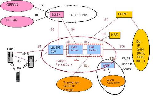
In E-UTRAN, eNBs provide the E-UTRA user plane protocols (PDCP/RLC/MAC/PHY) and control plane (RRC) protocol which terminates towards the UE.
The eNBs are interconnected with each other by means of the X2 interface. The eNBs are connected by the S1 interface to the EPC (Evolved Packet Core). The eNB connects to the MME (Mobility Management Entity) by means of the S1-MME interface and to the Serving Gateway (S-GW) by means of the S1-U interface. The S1 interface supports a many-to-many relation between MMEs / Serving Gateways and eNBs.
Air Interface
LTE physical layer multiple access scheme is based on Orthogonal Frequency Division Multiplexing (OFDM) with a cyclic prefix (CP) in the downlink, and on Single-Carrier Frequency Division Multiple Access (SC-FDMA) with a cyclic prefix in the uplink. LTE supports two duplex modes: Frequency Division Duplex (FDD), supporting full duplex and half duplex operation, and Time Division Duplex (TDD).
For FDD, radio frame structure type 1 is used and has duration of 10ms and consists of 20 slots with a slot duration of 0.5ms. Two adjacent slots form one sub-frame of length 1ms.
For TDD, radio frame structure type 2 is used and consists of two half-frames with a duration of 5ms each and containing each 8 slots of length 0.5ms and three special fields (DwPTS, GP and UpPTS).